
This example compares the effective lengths and critical load factor, which can be calculated in RFEM 6 using the Structure Stability add-on, with a manual calculation. The structural system is a rigid frame with two additional hinged columns. This column is loaded by vertical concentrated loads.

A reinforced concrete beam is designed as a two-span beam with a cantilever. The cross-section varies along the length of the cantilever (tapered cross-section). The internal forces, the required longitudinal and shear reinforcement for the ultimate limit state are calculated.

In this verification example, the capacity design values of shear forces on beams are calculated in accordance with EN 1998-1, 5.4.2.2 and 5.5.2.1 as well as the capacity design values of columns in flexure in accordance with 5.2.3.3(2). The system consists of a two span reinforced concrete beam with a span length of 5.50m. The beam is part of a frame system. The results obtained are compared with those in [1].
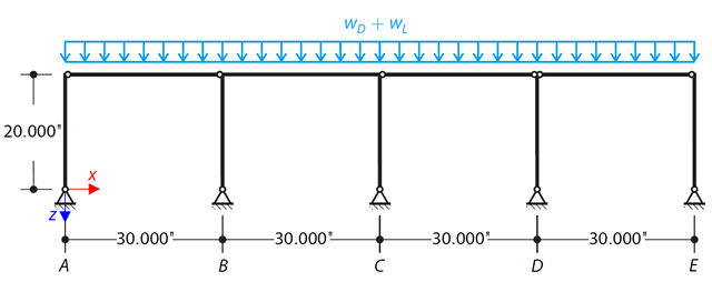
Determine the required strengths and effective length factors for the ASTM A992 material columns in the moment frame shown in Figure 1 for the maximum gravity load combination, using LRFD and ASD.
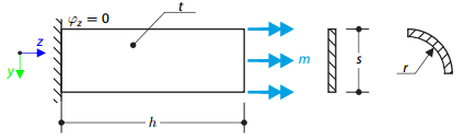
A thin plate is fixed on one side and loaded by means of distributed torque on the other side. First, the plate is modeled as a planar plate. Furthermore, the plate is modeled as one-fourth of the cylinder surface. The width of the planar model is equal to the length of one-fourth of the circumference of the curved model. The curved model thus has almost equal torsional constant to the planar model.
Determine the required strengths and effective length factors for the ASTM A992 material columns in the moment frame shown in Figure 1 for the maximum gravity load combination, using LRFD and ASD.
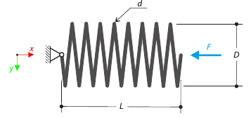
A closely coiled helical spring is loaded by a compression force. The spring has middle diameter D, wire diameter d, and it consists of i turns. The total length of the spring is L. Determine the total deflection of the spring for the member model and one‑turn deflection for the solid model.
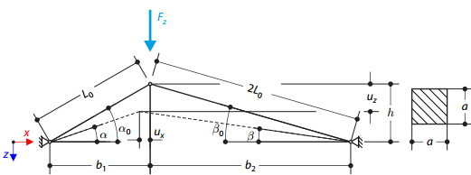
A structure is made of two trusses of unequal length, which are embedded into the hinge supports. The structure is loaded by concentrated force. The self-weight is neglected. Determine the relationship between the loading force and the deflection, considering large deformations.
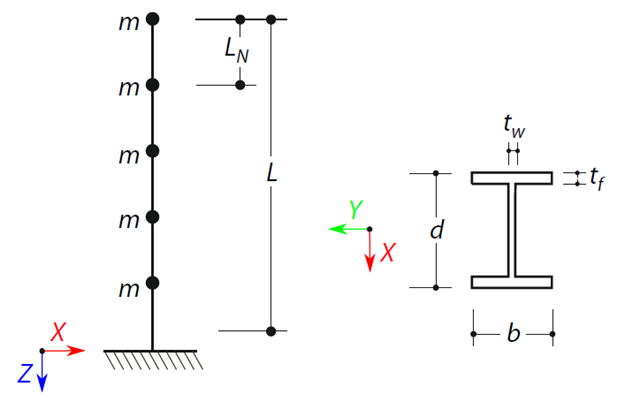
A cantilever beam with an I-beam cross-section of length L is defined. The beam has five mass points with masses m acting in the X-direction. The self-weight is neglected. The frequencies, mode shapes, and equivalent loads of this 5-DOF system are analytically calculated and compared with the results from RSTAB and RFEM.